
March 20, 2024
Enhancing API Plan 31 Systems: Best Practices for Reliability
API Plan 31 is a configuration used for sealing arrangements in pumps and other rotating equipment which process fluids containing suspended particles and solids.
In API (American Petroleum Institute) standards, it specifies a particular combination of seal components and auxiliary systems intended to prevent leakage from the pump. The primary components of API Plan 31 typically include a single mechanical seal, a cyclone separator and a piping system for flushing the seal faces with clean liquid.
The components of API Plan 31 typically include:
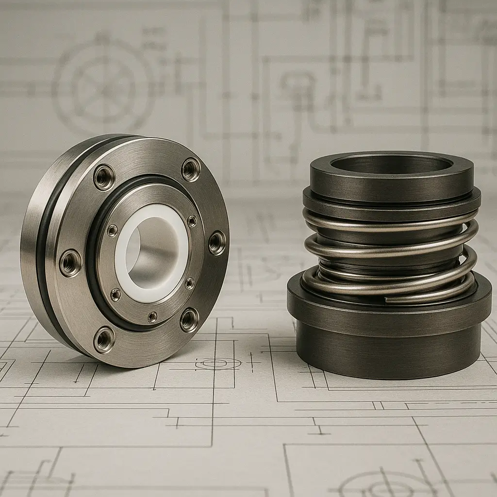
Mechanical Seal:
This is the primary seal that prevents leakage around the shaft of the pump. It consists of two flat faces pressed together with a mechanical force to create a seal. One face rotates with the shaft, while the other is stationary.
Flush Liquid:
Flushed liquid in a Plan 31 system is recirculated from the discharge of the pump, through a cyclone separator and to the mechanical seal. The Cyclone separator helps to separate the solids in the liquid and direct substantially clean fluid to the mechanical seal, with the solids directed back to pump suction. The purpose of the flush liquid is to provide cooling and lubrication to the seal faces.
Unlike API Plan 11, a Plan 31 system is required when the pump is processing dirty liquids containing solids and suspended particles.
While API Plan 31 is designed to mitigate leakage and maintain the integrity of the mechanical seal, it is not without its problems. Some of the issues associated with API Plan 31 include:
Reliability:
The cyclone separator efficiency is proportional to the cyclone diameter. A large cyclone diameter leads to less efficient separation, whereas a smaller cyclone diameter provides more efficient separation. Clearly, smaller cyclone diameters can clog quicker than large cyclone diameters, so selecting the correct cyclone separator size for the application is important.
Issues:
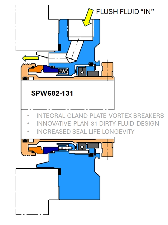
It will be obvious to the experienced reader that no matter how efficient the cyclone separator is, it will not separate all suspended particles from processed fluid. Therefore some particles and solids will be directed to the seal faces of the mechanical seal. If the flush orifice is directly over the seal faces, the suspended particles will act to "shot blast" the seal faces which could lead to damage and premature seal leakage. Therefore, Plan 31 mechanical seal should not be designed with the flush orifice directly over the sealing interface, and specifically it should be positioned away from the stationary seal face, as the stationary seal face is static and doesn't rotate to help mitigate any shot-blasting target points.
It is important that Plan 31 systems are used for applications containing solids with specific gravity at twice (or more) than that of process fluid. Cyclone separators will not function correctly and separate particles which are too small/light.
Overall, while API Plan 31 can be effective in certain applications containing suspended particles/solids, it is important to carefully consider its drawbacks and ensure proper design, installation, and maintenance of the mechanical seal, system and pump in order to minimize problems and optimize rotating equipment performance and reliability. Also remember that not all Plan 31 systems are the same. Seal design improvements and best practice techniques make a significant difference to how successful the Plan 31 system will be. Some of these best practice Plan 31 techniques are discussed below.
Best Practice:
API Plan 31 system should use used with a throat bushing in the bottom of the seal chamber of the pump. This helps to isolate the solid particles in the pump suction end, and help prevent them entering the seal chamber.
The size of the flush orifice should be a minimum of 6mm (1/4") given suspended particles can eventually clog very small orifices such as 3mm (1/8") or less.
The gland plate of the mechanical seal should incorporate an vortex breaker. The vortex breaker helps to prevent the wear damage on the mechanical seal and pump. Abrasives rotating in a centrifugal motion will quickly wear components and lead to premature seal failure.

The inside surfaces of the cyclone separator will wear during operation. The speed of the wear will depend on the abrasiveness of the processed fluid media and the wear resistance/hardness of the separator material.
If separator wear goes unmonitored, and separator wall thickness gets to a critical level, it could lead to catastrophic failure of the separator and system. Regular cyclone separator inspection is mandatory in a Plan 31 application.
Taking periodical samples of the process media entering the mechanical seal is advisable. If the separator wears, metallic particles will be present in the sample collector pot. If the separator is incorrectly sized, the percentage solids will be high in the sample collection pot. There are many indicative failure warning signs in any system, therefore best practice engineers provide for a process media sample collection in Plan 31 systems.

At Reliability, we offer a range of products and expert guidance tailored to enhance the reliability of API Plan 31 systems. Explore our offerings:
Reach out to us for more information on optimising your sealing arrangements. Contact us.