
Plan 23E
The Plan 23E system is an innovative adaption of the conventional API Plan 23 system, providing enhanced seal face cooling for optimised mechanical seal performance in medium temperature applications.
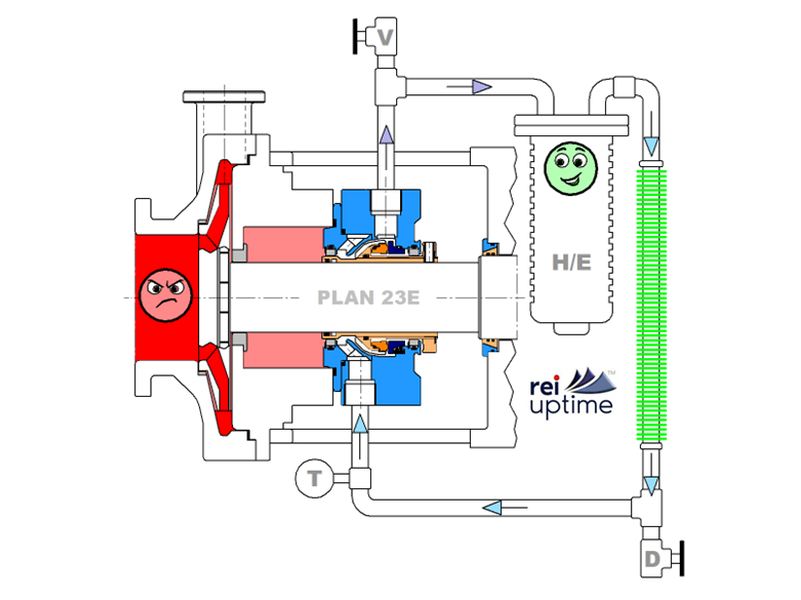
In the Plan 23E system, the process fluid is forced circulated from the mechanical seal chamber (the mechanical seal flush port) to a heat exchanger and back to the mechanical seal chamber. The mechanical seal chamber is separated from the pump seal chamber by a floating restriction bush. This optimises the sealing environment, as the volume of fluid circulated in the Plan 23 is less than 1/10th of the conventional Plan 23 system. This means the heat exchanger doesn't need to work as hard whilst still providing cool fluid to the mechanical seal faces in, what would otherwise be a high temperature environment.
In the Plan 23E system water cooled heat exchanger is replaced by an air cooled heat exchanger with the optional connection to a bank of hybrid air-cooled finned tubes. This system therefore eliminates the need for the piping and associated costs of the water cooling system, making it an ideal environmentally friendly adaptation which is applicable for many medium temperature applications, typically up to 250 Deg C (480 Deg F).
Unlike Plan 32, there is no process fluid temperature reduction. This means that there is no wasted energy input heating the fluid inside the process pump.
Unlike Plan 32, there is no process fluid concentration dilution, as there is no external fluid supplied into the pump sealing chamber.
Furthermore, unlike Plan 21, the heat exchanger doesn't have to work as hard. This means, in a like-for-like application, the cooling water supply to the heat exchanger can be reduced.
There are typically HUGE operational savings to be made from Plan 23E applications, which far exceed any small, one off capital investment in the Plan 23E heat exchanger circuit.
Important - The key element to maximise the benefit of the Plan 23E system is in the PUMPING RING design and the HEAT EXCHANGER design. Reliability Seals have the best innovations for both. Also, check out Plan 23S systems and Plan 23B system adaptions for further enhanced operational performance.
Features
- The standard Plan 23E system includes an air cooled heat exchanger, temperature gauge, vent valve and drain valve AND a integral floating restriction bush between the pump seal chamber and the mechanical seal chamber.
- The cartridge mechanical seal incorporates an integral fluid circulation device or pumping ring, which circulates process fluid in a substantially closed loop.
- Preferably the heat exchanger is water cooled for extreme temperature applications.
- Preferably, the pumping ring design is of an angled design with large radial clearances which confirm to the best practice requirements of the API682 standard.
- When the pump is not running, heat transfer is achieved by fluid convection process. When the pump is running, heat transfer is achieved by the ring.
Benefits
- Plan 23E reduces the volume of process fluid circulated in the Plan23 system by up to 90% compared to a conventional Plan 23 system. This reduces the heat load on the heat exchanger allowing an air-cooled heat exchanger with optional additional finned tubing to be used which eliminates the need for water consumption/costs in a conventional water cooled heat exchanger. This is therefore the best environmental solution.
- Plan 23E provides excellent, low temperature process fluid within the closed loop system. This helps to optimise seal face fluid film conditions, extending mechanical seal life.
- Plan 23E does not use an external fluid source that increases cost and/or heat input and energy usage.
- Plan 23E establishes required margin between fluid vapour pressure and seal chamber pressure.
- Plan 23E is much more efficient than a Plan 21 system as only the fluid in the seal chamber is circulated through the heat exchanger.
Drawbacks
- High viscosity products can affect the process fluid circulation performance. Therefore the selection of the most appropriate seal pumping ring, with high delivery capabilities is important. Reliability seals can provide advice on best practice pumping ring design.
Applications
- Plan 23E systems can be employed in any temperature related application, typically over 100 DegC (200 deg F) to 250 Deg C (480 Deg F), as cool seal faces last longer and increase equipment reliability
- Plan 23E is especially suited for hot and clean process fluid applications
- Typical applications include boiler feed and boiler water, and hot oil hydrocarbon services as found in the Oil and Gas sector.
- Check out the Reliability Seals Plan 23S system - inclusion of an integral sample collection pot, for in-process periodic inspection of the fluid in the mechanical seal chamber.
Warning Notes
- The selection of the heat exchanger is important. Compact Shell and Tube, high-efficiency heat exchangers provide excellent cooling and can be used in restricted spaces due to their compact design.
- The selection of the pumping ring is also important. Close radial clearance parallel design pumping rings should be avoided as the they need very close radial clearances (0.5mm or 0.020") to operate. Depending on the age/condition of the process pump, its shaft bearing support and the setting of the seal to the pump, metal to metal contact can result with close radial clearance designs. Tapered pumping ring designs are by far a more superior solution as the radial clearance between stationary and rotary components is much greater whilst circulating the same, or greater amounts of fluid.
- The cooling water to the heat exchanger should ideally by soft water for optimised heat transfer and to minimise scale build up inside the pipework and heat exchanger. Periodic checks of the heat exchanger are recommended.
- If their is no plant water supply, or plant ring main system which can supply cooling fluid to the heat exchanger, Reliability Seals can provide an innovative, closed loop Plan 54 system to supply the heat exchanger.
- The position of the heat exchanger should be as close as possible to the seal chamber / mechanical seal, to optimise the Plan 23 fluid pumping circuit.